
 Order Now!
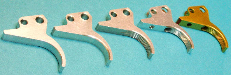
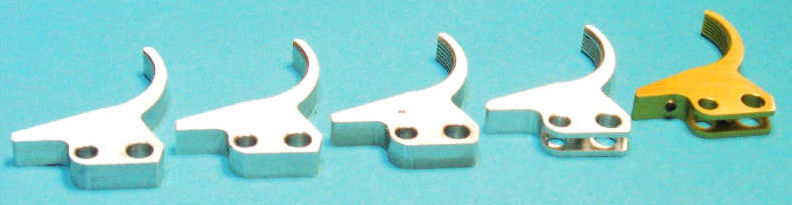
10 Stages of GRT-III Trigger Manufacture
(click on images below to view larger)


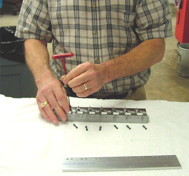
This shows using an 8 place jig
The GRT-III manufacturing process described here will give you a pretty good idea of just how involved in making the GRT-III trigger is.
The GRT-III Trigger, though in appearance seems to be quite simple, is a very complex, intricate and precisely machined part. Below is an overview of the manufacturing process (with pictures above) in a nutshell so that you may see what is fundamentally involved and just why it is so effective, efficient and such a success. Some of the manufacturing processes, procedures and measurements are vague with intent. The GRT-III manufacturing process would be extremely difficult to duplicate.
Make a Trigger Prototype:
Of course you need a prototype design to start out with. This provides the basic design and configuration.
Make a basic Dimensional Drawing:
From that prototype, an initial dimensional drawing needs to be made and a measurement point of reference is determined. This point of reference is used to determine any and all of the other points of measurements used in and for the CNC machine programming.
The triggers are cut from Aluminum bar stock : inch by 2 inch by 8ft. The stock is cut down to the desired lengths to fit the jig. The prototype jig, used for testing and design, is designed to hold and cut a single trigger while this Master jig is designed to hold and cut 8 triggers at a time.
Building a basic CNC program to cut out trigger (the beginning of the Master program).
The Master program consists of many phases or sub-programs. As each phase of the milling process is set up and tested and approved, it is then added to the master program in the proper sequence of the manufacturing process.
Making the jigs is and must be extremely precise and is complex and time consuming process as is developing the program for the CNC machine and very expensive to say the least. It takes the sales just to pay for this aspect of the manufacturing costs. And:if any error are made, it is very costly, usually a total loss.
Make a 1st stage prototype mounting hole setup jig and test:
Build the program for the 8 place 1st stage mounting hole setup
Make permanent 8 place 1st machining stage mounting hole setup jig:
In order to be able to mill out something it has to be able to be held securely and exactly in place each and every time, time after time. There is no room for error here or anywhere else in the milling operations.
Preparing the plate for cutting:
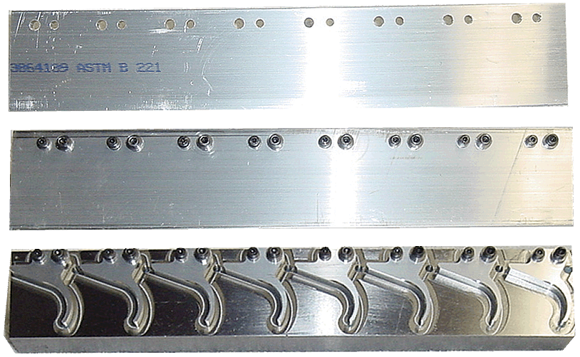
This jig is used to perform the operation of drilling out 16 precisely located holes, 2 in each trigger of two different precise diameters in the raw material. This is done in four passes on the CNC machine, one for each size hole per trigger and then each hole is reamed with a precision reamer to an exact diameter within five 10,000th of an inch.
The part is then removed from the jig and all 16 holes per side, both sides, for a total of 32 holes, are slightly chamfered by hand to remove sharp edges. It can now be mounted in the Master jig and be fitted precisely and held in place.
Make a Prototype 2nd stage cutout Jig and test
Make two permanent 8 place 2nd stage Jig (Master Jigs)
Build program for 2nd machining stage setup
Build chamfer pass program side :A: , and incorporate sub program into Master CNC program
This jig is used to mount the plates that we drilled the mounting holes into for cutting out the trigger itself. Once mounted using 16 screws, the CNC machine cuts the 8 triggers out using three passes per trigger. The first pass is the cutout, the second pass is the rough cut and the final pass is the finish cut. That is a total of 24 cuts per jig. Then, the 8 triggers are partially chamfered on side A where the finger sets. That is a total of 32 passes on the jig for just this phase of the operation.
Every time the finished stage of the mounted material is removed from the jig, the jig is thoroughly cleaned prior to mounting new material as is the new plate going in. One tiny piece of trash on the surface of either piece can easily ruin that piece.
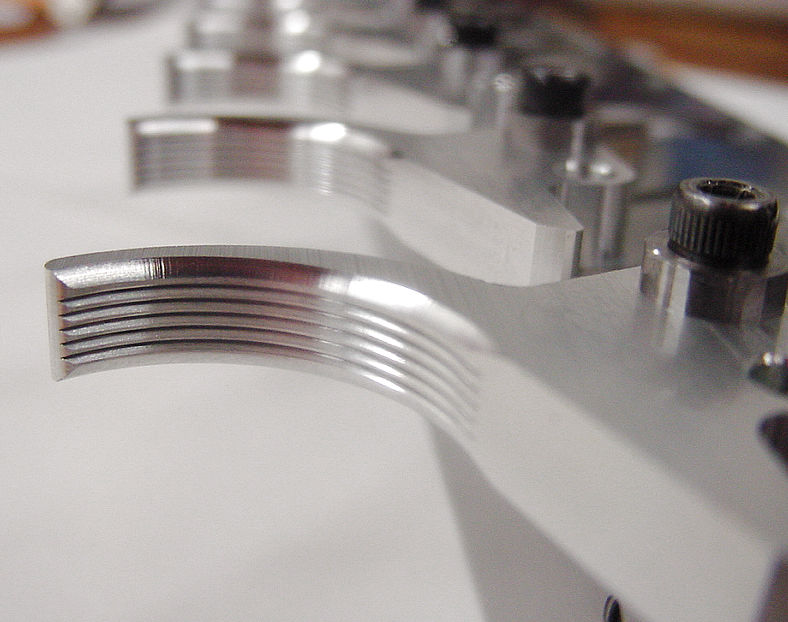
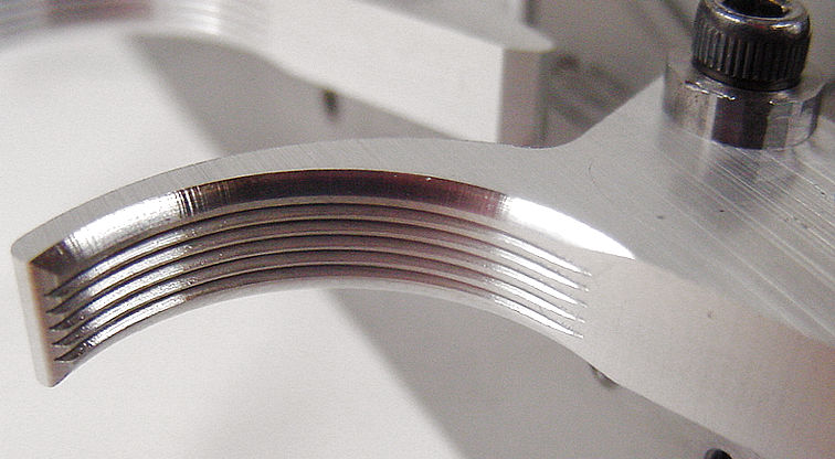
Build chamfer pass program side :B: add sub program to Master CNC program
Build finger pad cuts program, four individual operations, side :B: and incorporate sub-program into Master CNC program
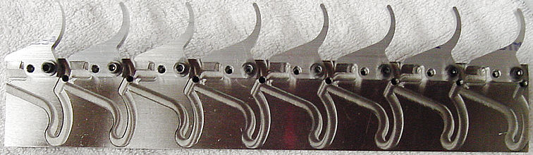
The cut out triggers are complete on side A. The jig is removed from the CNC machine, the 16 mounting screws are removed from the triggers and the triggers removed from the jig. They are then inverted and turned 180 degrees and re-mounted with the screws to the jig and reinstalled in the CNC machine to finish side B.
Side B of the trigger is now chamfered and the four individually cut lines for the finger pad are now cut into the trigger. That makes 5 cuts in 8 triggers for 40 more cuts.
The triggers are now removed from the jigs and the basic roughed in trigger is now complete but far from finished. From this point, it goes into several semi-manual phases of manufacturing.
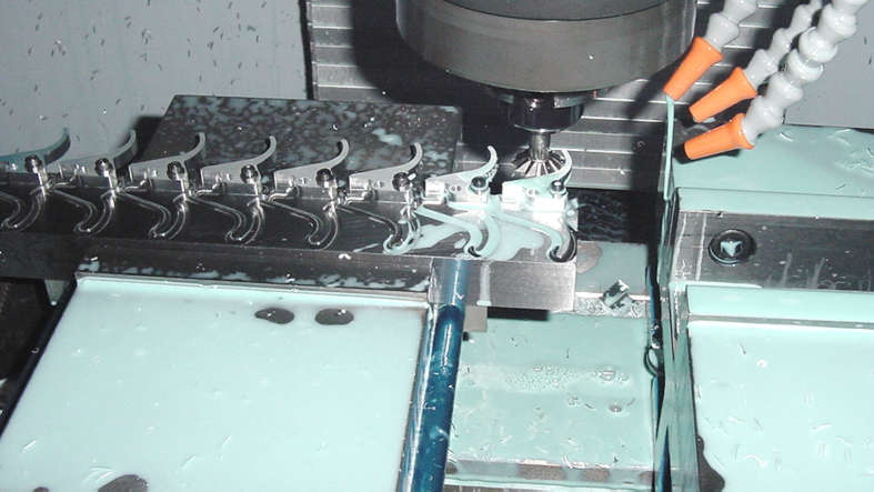
Next, the triggers are each individually milled one at a time in four passes on a computer controlled milling machine. The trigger is mounted into a jig and the lever slot is now be machined in to a specified depth and width. Based on one master jig of triggers, that:s 40 cut/passes.
Milling and drilling in the adjustment stages:
A slight flat surface is milled in the slightly curved area of the trigger where the 1st stage adjustment will be drilled later in the process. This flat surface keeps the drill/tap bit from canting due to the drilling angle and breaking later.
The recessed hole for the 2nd stage adjustment screw is drilled to a specified depth. The hole for the adjustment screw itself is drill/tapped and must be drilled accurately within a very close tolerance.
Next the 1st stage hole is drilled for tapping. The final tapping for the 1st stage adjustment screw is done later after the trigger is anodized.
For all intent and purposes, the machining part of the GRT-III trigger is now complete.
Holy smokes:.
What this boils down to is that there are over 210 cutting, milling, drilling and tapping operations per each master jig of triggers or more than 26 operations per trigger to this point. That does not include the installation and removal of the 16 mounting screws per jig each time during the loading and unloading of the jigs for the different stages of operations as they progress.
Then a number of the triggers at a time are placed into a tumbler along with thousands of small stainless steel ball bearings and tumbled for about twenty minutes to smooth out any remaining sharp edges. Now the trigger blades are individually sanded by hand on a sanding wheel, finished on on the sides to remove the majority of any small scratch marks. washed and prepared to be sent out to be anodized. The GRT-III trigger blades are now anodized for color, as well as resistance to wear and corrosion.
After returning from being anodized, the final step is mounting each of the triggers individually into a jig for the tapping of the 1st stage adjustment hole. The manufacturing process is now finally complete.
It is now prepared for final assembly. The tension spring for the 2nd stage adjustment is cut from a length of stock wire and the 2nd stage stainless adjustment screw and tension spring are then installed. The Allen head 1st stage adjustment screw is installed and seated with care to its approximate proper depth.
And finally, it:s tested and prepared to ship.
Each and every GRT-III trigger is now placed into a Gamo trigger housing where it is tested and both the 1st and 2nd stages are adjusted to a point that would be acceptable to almost all shooters making it a true drop in modification. It is removed then from the trigger housing, placed in a poly bag with the .050 Allen tool and readied to be sent to its proud new owner.
When ordered, it then is placed into a bubble wrap envelope, address label printed out, sealed, stamped and taken to the post office and mailed out.
There you are:as simple as that:and all of that for a mere $28.50 plus postage and handling....lol:
Thank you